Filter cleaning controller SOP 06
SOP 06
The filter cleaning controller SOP 06 constantly checks the correct operation of the valve
UP TO 6 VALVES
The number of connected valves can be set in the control panel from 1 to 6
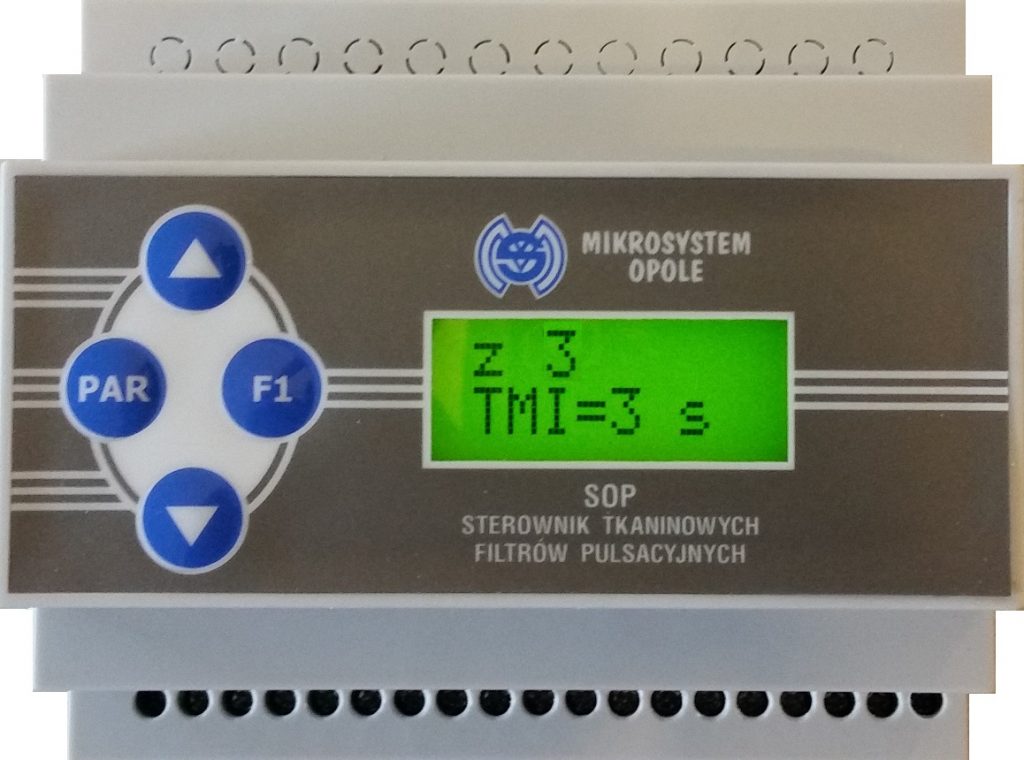
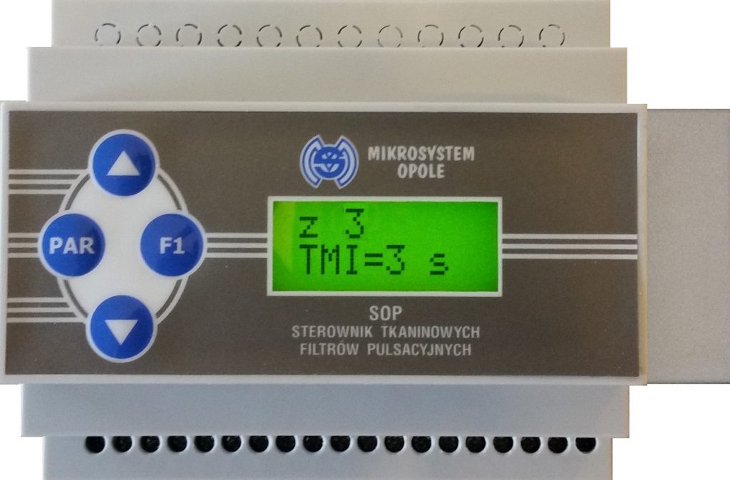
The SOP 06 controller is a microprocessor-based electronic system. The controller is mounted in a small plastic housing. It can be powered directly by 230V AC mains voltage. The controller must be installed on a 35 mm DIN rail. The system works in cyclical mode. In cyclic mode, all connected valves are switched on successively for the duration of the pulse. After the pulse of each valve, the time between pulses is counted down. After the last valve pulse, the system counts down the time between cycles and starts operation from the beginning – from the first valve. The controller constantly checks the correct operation of the valves and in the event of a fault an alarm is generated. The controller is equipped with an operator panel with a 2 x 8 character LCD screen mounted on the top cover of the controller, enabling parameter setting and system operation control.
System Data:
- Digital outputs (24V DC / 1.6A) Valve control ……… 6 pcs.
- Digital input (start / stop) of regeneration ……… 1 pcs.
- Relay output (normally open contact) 2A / 230V AC (alarm signal) ……… 1 pcs.
- Valve supply voltage ……… 24V DC
- Maximum power consumed by the valve ……… 25 W
- Pulse time range [Tp] ……… 0.05 – 0.30 sec.
- Range of intervals between pulses [Tbp] ……… 3 – 250 sec.
- Pause range between cycles [Tbc] ……… 0 – 60 min.
- Controller supply voltage ……… 230 V AC, 50 Hz, 50 W
- Dimensions (width-height-depth) ……… 106x90x57 mm
Catalog card
PDF diagram
CE declaration
Filter cleaning controller SOP 06P
SOP 06P
The filter cleaning controller SOP 06P constantly checks the correct operation of the valve
UP TO 6 VALVES – PRESSURE DIFFERENTIAL SENSOR
The number of connected valves can be set in the control panel from 1 to 6
The SOP 06P controller is a microprocessor based electronic system equipped with a pressure difference sensor. The controller is mounted in a small plastic housing. It can be powered directly by 230V AC mains voltage. The controller must be installed on a 35 mm DIN rail. The system works in cyclic or automatic mode. In cyclic mode, all connected valves are switched on successively for the duration of the pulse. After the pulse of each valve, the time between pulses is counted down. After the last valve pulse, the system counts down the time between cycles and starts operation from the beginning – from the first valve. In automatic mode, the control algorithm constantly controls the value of the pressure difference across the filter. After exceeding the set dP limit, the system turns on the valve. The next valve is activated when the differential pressure is still greater than the dP limit. The controller constantly checks the correct operation of the valves, and in the event of a fault an alarm is generated. The controller is equipped with an operator panel with a 2 x 8 character LCD screen mounted on the top cover of the controller, enabling parameter setting and system operation control.
System Data:
- Digital outputs (24V DC / 1.6A) Valve control ……… 6 pcs.
- Digital input (start / stop) of regeneration ……… 1 pcs.
- Relay output (normally open contact) 2A / 230V AC (alarm signal) ……… 1 pcs.
- Valve supply voltage ……… 24V DC
- Maximum power consumed by the valve ……… 25 W
- Pulse time range [Tp] ……… 0.05 – 0.30 sec.
- Range of intervals between pulses [Tbp] ……… 3 – 250 sec.
- Pause range between cycles [Tbc] ……… 0 – 60 min.
- Differential pressure measuring range ……… 0 – 5,0 kPa
- Pressure differential threshold setting range (regeneration) ……… 0,2 – 4,4 kPa
- Pressure differential threshold setting range (alarm) ……… 0,2 – 5,0 kPa
- Controller supply voltage ……… 230 V AC, 50 Hz, 50 W
- Connectors for connecting the medium from the filter chambers ……… Fi6/4
- Dimensions (width-height-depth) ……… 126x90x57 mm
Catalog card
PDF diagram
CE declaration
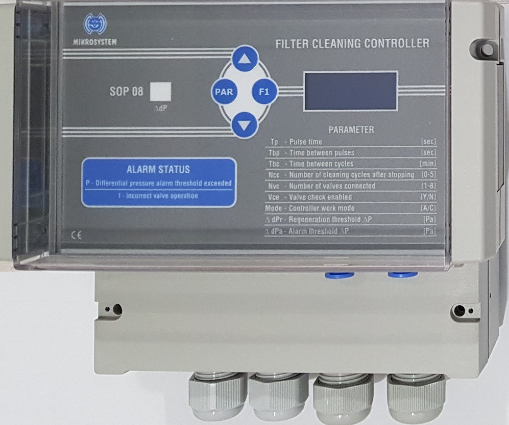
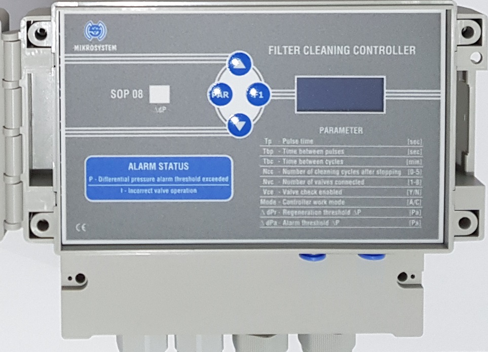
Filter cleaning controller SOP 08
SOP 08
The filter cleaning controller SOP 08 constantly checks the correct operation of the valve
UP TO 8 VALVES
The number of connected valves can be set in the control panel from 1 to 8
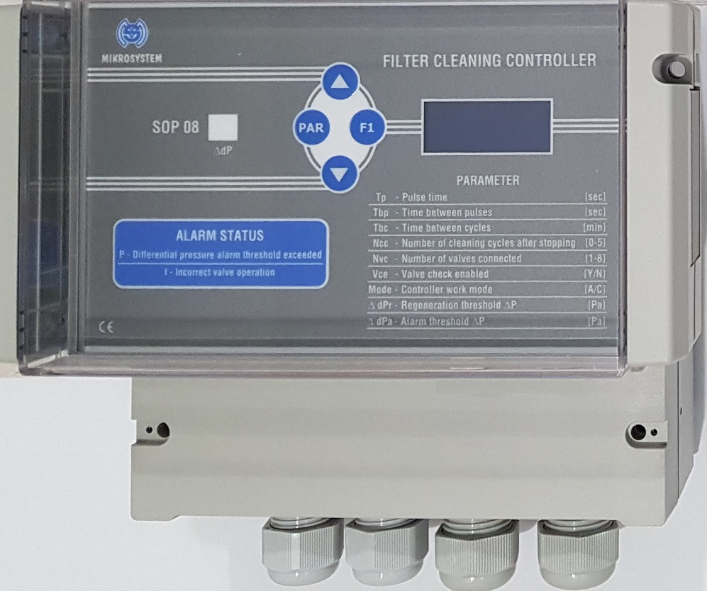
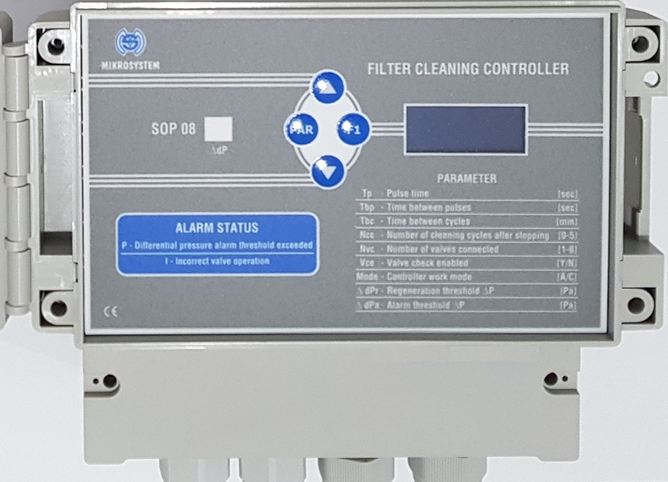
The controller is mounted in a small plastic housing with IP65 protection. It can be powered directly by 230V AC mains voltage. The controller can be installed both on a 35 mm DIN rail and on a filter construction. The system works in cyclical mode. In cyclic mode, all connected valves are switched on successively for the duration of the pulse. After the pulse of each valve, the time between pulses is counted down. After the last valve pulse, the system counts down the time between cycles and starts operation from the beginning – from the first valve. The controller constantly checks the correct operation of the valves and in the event of a fault an alarm is generated. The number of connected valves can be set in the control panel from 1 to 8. The controller is equipped with an operator panel with a 2 x 8 character LCD screen mounted on the top cover of the controller, enabling parameter setting and system operation control. The controller is placed in a dustproof IP65 housing with a safety flap adapted for closing with a padlock.
System Data:
- Digital outputs (24V DC / 1.6A) Valve control ……… 8 pcs.
- Digital input (start / stop) of regeneration ……… 2 pcs.
- Relay output (normally open contact) 2A / 230V AC (alarm signal) ……… 1 pcs.
- Valve supply voltage ……… 24V DC
- Maximum power consumed by the valve ……… 36 W
- Pulse time range [Tp] ……… 0.05 – 0.50 sec.
- Range of intervals between pulses [Tbp] ……… 3 – 250 sec.
- Pause range between cycles [Tbc] ……… 0 – 60 min.
- Controller supply voltage ……… 230 V AC, 50 Hz, 50 W
- Dimensions (width-height-depth) ……… 166x161x121 mm
Filter cleaning controller SOP 08P
SOP 08P
The filter cleaning controller SOP 08P constantly checks the correct operation of the valve
UP TO 8 VALVES – PRESSURE DIFFERENTIAL SENSOR
The number of connected valves can be set in the control panel from 1 to 8
The controller is mounted in a small plastic housing with IP65 protection. It can be powered directly by 230V AC mains voltage. The controller can be installed both on a 35 mm DIN rail and on a filter construction. The system works in cyclic or automatic mode. In automatic mode, the control algorithm constantly checks the value of the pressure difference across the filter. After exceeding the set dP limit, the system turns on the valve for a pulse time. The next valve is activated after the time between pulses when the pressure difference is still greater than the limit value dP. If the set dP alarm value is exceeded, an alarm is generated. In cyclic mode, all connected valves are switched on successively for the duration of the pulse. After the pulse of each valve, the time between pulses is counted down. After the last valve pulse, the system counts down the time between cycles and starts operation from the beginning – from the first valve. The controller constantly checks the correct operation of the valves and in the event of a fault an alarm is generated. The number of connected valves can be set in the control panel from 1 to 8. The controller is equipped with an operator panel with a 2 x 8 character LCD screen mounted on the top cover of the controller, enabling parameter setting and system operation control. The controller is placed in a dustproof IP65 housing with a safety flap adapted for closing with a padlock.
System Data:
- Digital outputs (24V DC / 1.6A) Valve control ……… 8 pcs.
- Digital input (start / stop) of regeneration ……… 2 pcs.
- Relay output (normally open contact) 2A / 230V AC (alarm signal) ……… 1 pcs.
- Analog output dP 0 – 5,0 kPa ……… 4-20mA (max. 500 ohm)
- Valve supply voltage ……… 24V DC
- Maximum power consumed by the valve ……… 36 W
- Pulse time range [Tp] ……… 0.05 – 0.50 sec.
- Range of intervals between pulses [Tbp] ……… 3 – 250 sec.
- Pause range between cycles [Tbc] ……… 0 – 60 min.
- Differential pressure measuring range ……… 0 – 5,0 kPa
- Pressure differential threshold setting range (regeneration) ……… 0,2 – 4,4 kPa
- Pressure differential threshold setting range (alarm) ……… 0,2 – 5,0 kPa
- Controller supply voltage ……… 230 V AC, 50 Hz, 50 W
- Connectors for connecting the medium from the filter chambers ……… Fi6/4
- Dimensions (width-height-depth) ……… 166x161x121 mm
Filter cleaning controller SOP 08 (85-264V)
SOP 08 (85-264V)
The filter cleaning controller SOP 08 (85-264V) constantly checks the correct operation of the valve
UP TO 8 VALVES
The number of connected valves can be set in the control panel from 1 to 8
The controller is mounted in a small plastic housing with IP65 protection. It can be powered directly by 85-264V AC mains voltage. The controller can be installed both on a 35 mm DIN rail and on a filter construction. The system works in cyclical mode. In cyclic mode, all connected valves are switched on successively for the duration of the pulse. After the pulse of each valve, the time between pulses is counted down. After the last valve pulse, the system counts down the time between cycles and starts operation from the beginning – from the first valve. The controller constantly checks the correct operation of the valves and in the event of a fault an alarm is generated. The number of connected valves can be set in the control panel from 1 to 8. The controller is equipped with an operator panel with a 2 x 8 character LCD screen mounted on the top cover of the controller, enabling parameter setting and system operation control. The controller is placed in a dustproof IP65 housing with a safety flap adapted for closing with a padlock.
System Data:
- Digital outputs (24V DC / 1.6A) Valve control ……… 8 pcs.
- Digital input (start / stop) of regeneration ……… 2 pcs.
- Relay output (normally open contact) 2A / 230V AC (alarm signal) ……… 1 pcs.
- Valve supply voltage ……… 24V DC
- Maximum power consumed by the valve ……… 36 W
- Pulse time range [Tp] ……… 0.05 – 1.00 sec.
- Range of intervals between pulses [Tbp] ……… 3 – 250 sec.
- Pause range between cycles [Tbc] ……… 0 – 60 min.
- Controller supply voltage ……… 85-264V AC, 50 Hz, 50 W
- Dimensions (width-height-depth) ……… 166x161x121 mm
Filter cleaning controller SOP 08P (85-264V)
SOP 08P (85-264V)
The filter cleaning controller SOP 08P (85-264V) constantly checks the correct operation of the valve
UP TO 8 VALVES – PRESSURE DIFFERENTIAL SENSOR
The number of connected valves can be set in the control panel from 1 to 8
The controller is mounted in a small plastic housing with IP65 protection. It can be powered directly by 85-264V AC mains voltage. The controller can be installed both on a 35 mm DIN rail and on a filter construction. The system works in cyclic or automatic mode. In automatic mode, the control algorithm constantly checks the value of the pressure difference across the filter. After exceeding the set dP limit, the system turns on the valve for a pulse time. The next valve is activated after the time between pulses when the pressure difference is still greater than the limit value dP. If the set dP alarm value is exceeded, an alarm is generated. In cyclic mode, all connected valves are switched on successively for the duration of the pulse. After the pulse of each valve, the time between pulses is counted down. After the last valve pulse, the system counts down the time between cycles and starts operation from the beginning – from the first valve. The controller constantly checks the correct operation of the valves and in the event of a fault an alarm is generated. The number of connected valves can be set in the control panel from 1 to 8. The controller is equipped with an operator panel with a 2 x 8 character LCD screen mounted on the top cover of the controller, enabling parameter setting and system operation control. The controller is placed in a dustproof IP65 housing with a safety flap adapted for closing with a padlock.
System Data:
- Digital outputs (24V DC / 1.6A) Valve control ……… 8 pcs.
- Digital input (start / stop) of regeneration ……… 2 pcs.
- Relay output (normally open contact) 2A / 230V AC (alarm signal) ……… 1 pcs.
- Analog output dP 0 – 5,0 kPa ……… 4-20mA (max. 500 ohm)
- Valve supply voltage ……… 24V DC
- Maximum power consumed by the valve ……… 36 W
- Pulse time range [Tp] ……… 0.05 – 1.00 sec.
- Range of intervals between pulses [Tbp] ……… 3 – 250 sec.
- Pause range between cycles [Tbc] ……… 0 – 60 min.
- Differential pressure measuring range ……… 0 – 5,0 kPa
- Pressure differential threshold setting range (regeneration) ……… 0,2 – 4,4 kPa
- Pressure differential threshold setting range (alarm) ……… 0,2 – 5,0 kPa
- Controller supply voltage ……… 85-264V AC, 50 Hz, 50 W
- Connectors for connecting the medium from the filter chambers ……… Fi6/4
- Dimensions (width-height-depth) ……… 166x161x121 mm
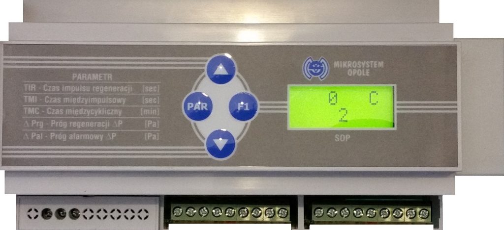
Filter cleaning controller SOP 12
SOP 12

The filter cleaning controller SOP 12 constantly checks the correct operation of the valve
UP TO 12 VALVES
The number of connected valves can be set in the control panel from 1 to 12
The SOP 12 controller is a microprocessor-based electronic system. The controller is mounted in a small plastic housing. It can be powered directly by 230V AC mains voltage. The controller must be installed on a 35 mm DIN rail. The system works in cyclical mode. In cyclic mode, all connected valves are switched on successively for the duration of the pulse. After the pulse of each valve, the time between pulses is counted down. After the last valve pulse, the system counts down the time between cycles and starts operation from the beginning – from the first valve. The controller constantly checks the correct operation of the valves and in the event of a fault an alarm is generated. The controller is equipped with an operator panel with a 2 x 8 character LCD screen mounted on the top cover of the controller, enabling parameter setting and system operation control.
System Data:
- Digital outputs (24V DC / 1.6A) Valve control ……… 12 pcs.
- Digital inputs (1: start / stop, 2: for example, compressed air control) ……… 2 pcs.
- Relay output (normally open contact) 2A / 230V AC (alarm signal) ……… 1 pcs.
- Valve supply voltage ……… 24V DC
- Maximum power consumed by the valve ……… 25 W
- Pulse time range [Tp] ……… 0.05 – 0.30 sec.
- Range of intervals between pulses [Tbp] ……… 3 – 250 sec.
- Pause range between cycles [Tbc] ……… 0 – 60 min.
- Controller supply voltage ……… 230 V AC, 50 Hz, 50 W
- Dimensions (width-height-depth) ……… 158x90x57 mm
Catalog card
PDF diagram
CE declaration
Filter cleaning controller SOP 12P
SOP 12P
The filter cleaning controller SOP 12P constantly checks the correct operation of the valve
UP TO 12 VALVES – PRESSURE DIFFERENTIAL SENSOR
The number of connected valves can be set in the control panel from 1 to 12
The SOP 12P controller is a microprocessor based electronic system equipped with a pressure difference sensor. The controller is mounted in a small plastic housing. It can be powered directly by 230V AC mains voltage. The controller must be installed on a 35 mm DIN rail. The system works in cyclic or automatic mode. In cyclic mode, all connected valves are switched on successively for the duration of the pulse. After the pulse of each valve, the time between pulses is counted down. After the last valve pulse, the system counts down the time between cycles and starts operation from the beginning – from the first valve. In automatic mode, the control algorithm constantly controls the value of the pressure difference across the filter. After exceeding the set dP limit, the system turns on the valve. The next valve is activated when the differential pressure is still greater than the dP limit. The controller constantly checks the correct operation of the valves, and in the event of a fault an alarm is generated. The controller is equipped with an operator panel with a 2 x 8 character LCD screen mounted on the top cover of the controller, enabling parameter setting and system operation control.
System Data:
- Digital outputs (24V DC / 1.6A) Valve control ……… 12 pcs.
- Digital inputs (1: start / stop, 2: for example, compressed air control) ……… 2 pcs.
- Relay output (normally open contact) 2A / 230V AC (alarm signal) ……… 1 pcs.
- Valve supply voltage ……… 24V DC
- Maximum power consumed by the valve ……… 25 W
- Pulse time range [Tp] ……… 0.05 – 0.30 sec.
- Range of intervals between pulses [Tbp] ……… 3 – 250 sec.
- Pause range between cycles [Tbc] ……… 0 – 60 min.
- Differential pressure measuring range ……… 0 – 5,0 kPa
- Pressure differential threshold setting range (regeneration) ……… 0,2 – 4,4 kPa
- Pressure differential threshold setting range (alarm) ……… 0,2 – 5,0 kPa
- Controller supply voltage ……… 230 V AC, 50 Hz, 50 W
- Connectors for connecting the medium from the filter chambers ……… Fi6/4
- Dimensions (width-height-depth) ……… 178x90x57 mm
Catalog card
PDF diagram
CE declaration
Filter cleaning controller SOP 08 V16 (85-264V)
SOP 08 V16 (85-264V)
The filter cleaning controller SOP 08 V16 (85-264V) constantly checks the correct operation of the valve
UP TO 16 VALVES
The number of connected valves can be set in the control panel from 1 to 16
The controller is mounted in a small plastic housing with IP65 protection. It can be powered directly by 85-264V AC mains voltage. The controller can be installed both on a 35 mm DIN rail and on a filter construction. The system works in cyclical mode. In cyclic mode, all connected valves are switched on successively for the duration of the pulse. After the pulse of each valve, the time between pulses is counted down. After the last valve pulse, the system counts down the time between cycles and starts operation from the beginning – from the first valve. The controller constantly checks the correct operation of the valves and in the event of a fault an alarm is generated. The number of connected valves can be set in the control panel from 1 to 16. The controller is equipped with an operator panel with a 2 x 8 character LCD screen mounted on the top cover of the controller, enabling parameter setting and system operation control. The controller is placed in a dustproof IP65 housing with a safety flap adapted for closing with a padlock.
System Data:
- Digital outputs (24V DC / 1.6A) Valve control ……… 16 pcs.
- Digital input (start / stop) of regeneration ……… 2 pcs.
- Relay output (normally open contact) 2A / 230V AC (alarm signal) ……… 1 pcs.
- Valve supply voltage ……… 24V DC
- Maximum power consumed by the valve ……… 36 W
- Pulse time range [Tp] ……… 0.05 – 1.00 sec.
- Range of intervals between pulses [Tbp] ……… 3 – 250 sec.
- Pause range between cycles [Tbc] ……… 0 – 60 min.
- Controller supply voltage ……… 85-264V AC, 50 Hz, 50 W
- Dimensions (width-height-depth) ……… 166x161x121 mm
Filter cleaning controller SOP 08P V16 (85-264V)
SOP 08P V16 (85-264V)
The filter cleaning controller SOP 08P V16 (85-264V) constantly checks the correct operation of the valve
UP TO 16 VALVES – PRESSURE DIFFERENTIAL SENSOR
The number of connected valves can be set in the control panel from 1 to 16
The controller is mounted in a small plastic housing with IP65 protection. It can be powered directly by 85-264V AC mains voltage. The controller can be installed both on a 35 mm DIN rail and on a filter construction. The system works in cyclic or automatic mode. In automatic mode, the control algorithm constantly checks the value of the pressure difference across the filter. After exceeding the set dP limit, the system turns on the valve for a pulse time. The next valve is activated after the time between pulses when the pressure difference is still greater than the limit value dP. If the set dP alarm value is exceeded, an alarm is generated. In cyclic mode, all connected valves are switched on successively for the duration of the pulse. After the pulse of each valve, the time between pulses is counted down. After the last valve pulse, the system counts down the time between cycles and starts operation from the beginning – from the first valve. The controller constantly checks the correct operation of the valves and in the event of a fault an alarm is generated. The number of connected valves can be set in the control panel from 1 to 16. The controller is equipped with an operator panel with a 2 x 8 character LCD screen mounted on the top cover of the controller, enabling parameter setting and system operation control. The controller is placed in a dustproof IP65 housing with a safety flap adapted for closing with a padlock.
System Data:
- Digital outputs (24V DC / 1.6A) Valve control ……… 16 pcs.
- Digital input (start / stop) of regeneration ……… 2 pcs.
- Relay output (normally open contact) 2A / 230V AC (alarm signal) ……… 1 pcs.
- Analog output dP 0 – 5,0 kPa ……… 4-20mA (max. 500 ohm)
- Valve supply voltage ……… 24V DC
- Maximum power consumed by the valve ……… 36 W
- Pulse time range [Tp] ……… 0.05 – 1.00 sec.
- Range of intervals between pulses [Tbp] ……… 3 – 250 sec.
- Pause range between cycles [Tbc] ……… 0 – 60 min.
- Differential pressure measuring range ……… 0 – 5,0 kPa
- Pressure differential threshold setting range (regeneration) ……… 0,2 – 4,4 kPa
- Pressure differential threshold setting range (alarm) ……… 0,2 – 5,0 kPa
- Controller supply voltage ……… 85-264V AC, 50 Hz, 50 W
- Connectors for connecting the medium from the filter chambers ……… Fi6/4
- Dimensions (width-height-depth) ……… 166x161x121 mm
Filter cleaning controller SOP 32
SOP 32
The filter cleaning controller SOP 32 constantly checks the correct operation of the valve
UP TO 32 VALVES
The number of connected valves can be set in the control panel from 1 to 32
The SOP 32 controller is a microprocessor-based electronic system. The controller is mounted in a small plastic housing. It can be powered directly by 230V AC mains voltage. The controller must be installed on a 35 mm DIN rail. The system works in cyclical mode. In cyclic mode, all connected valves are switched on successively for the duration of the pulse. After the pulse of each valve, the time between pulses is counted down. After the last valve pulse, the system counts down the time between cycles and starts operation from the beginning – from the first valve. The controller constantly checks the correct operation of the valves and in the event of a fault an alarm is generated. The controller is equipped with an operator panel with a 2 x 8 character LCD screen mounted on the top cover of the controller, enabling parameter setting and system operation control.
System Data:
- Digital outputs (24V DC / 1.6A) Valve control ……… 8 pcs.
- Digital outputs (24VDC / 1.6A) Section control ……… 4 pcs.
- Digital inputs (1: start / stop, 2: for example, compressed air control) ……… 2 pcs.
- Relay output (normally open contact) 2A / 230V AC (alarm signal) ……… 1 pcs.
- Valve supply voltage ……… 24V DC
- Maximum power consumed by the valve ……… 25 W
- Pulse time range [Tp] ……… 0.05 – 0.30 sec.
- Range of intervals between pulses [Tbp] ……… 3 – 250 sec.
- Pause range between cycles [Tbc] ……… 0 – 60 min.
- Controller supply voltage ……… 230 V AC, 50 Hz, 50 W
- Dimensions (width-height-depth) ……… 158x90x57 mm
Catalog card
PDF diagram
CE declaration
Filter cleaning controller SOP 32P
SOP 32P
The filter cleaning controller SOP 32P constantly checks the correct operation of the valve
UP TO 32 VALVES – PRESSURE DIFFERENTIAL SENSOR
The number of connected valves can be set in the control panel from 1 to 32
The SOP 32P controller is a microprocessor based electronic system equipped with a pressure difference sensor. The controller is mounted in a small plastic housing. It can be powered directly by 230V AC mains voltage. The controller must be installed on a 35 mm DIN rail. The system works in cyclic or automatic mode. In cyclic mode, all connected valves are switched on successively for the duration of the pulse. After the pulse of each valve, the time between pulses is counted down. After the last valve pulse, the system counts down the time between cycles and starts operation from the beginning – from the first valve. In automatic mode, the control algorithm constantly controls the value of the pressure difference across the filter. After exceeding the set dP limit, the system turns on the valve. The next valve is activated when the differential pressure is still greater than the dP limit. The controller constantly checks the correct operation of the valves, and in the event of a fault an alarm is generated. The controller is equipped with an operator panel with a 2 x 8 character LCD screen mounted on the top cover of the controller, enabling parameter setting and system operation control.
System Data:
- Digital outputs (24V DC / 1.6A) Valve control ……… 8 pcs.
- Digital outputs (24VDC / 1.6A) Section control ……… 4 pcs.
- Digital inputs (1: start / stop, 2: for example, compressed air control) ……… 2 pcs.
- Relay output (normally open contact) 2A / 230V AC (alarm signal) ……… 1 pcs.
- Valve supply voltage ……… 24V DC
- Maximum power consumed by the valve ……… 25 W
- Pulse time range [Tp] ……… 0.05 – 0.30 sec.
- Range of intervals between pulses [Tbp] ……… 3 – 250 sec.
- Pause range between cycles [Tbc] ……… 0 – 60 min.
- Differential pressure measuring range ……… 0 – 5,0 kPa
- Pressure differential threshold setting range (regeneration) ……… 0,2 – 4,4 kPa
- Pressure differential threshold setting range (alarm) ……… 0,2 – 5,0 kPa
- Controller supply voltage ……… 230 V AC, 50 Hz, 50 W
- Connectors for connecting the medium from the filter chambers ……… Fi6/4
- Dimensions (width-height-depth) ……… 178x90x57 mm
Catalog card
PDF diagram
CE declaration
Filter cleaning controller SOP 1N
SOP 1N
The filter cleaning controller SOP 1N constantly checks the correct operation of the valve
UP TO 40 VALVES – OPTIONALLY PRESSURE DIFFERENTIAL TRANSMITTER
A differential pressure transducer can be connected to the controller
The controller is mounted in a small plastic housing MODULBOX XT. The controller must be installed on a 35 mm DIN rail. The SOP1N controller is compatible with the previously manufactured SOP1A, SOP1B controllers. The system works in cyclic or automatic mode. In cyclic mode, all connected valves are switched on successively for the duration of the pulse. After the pulse of each valve, the time between pulses is counted down. After the last valve pulse, the system counts down the time between cycles and starts operation from the beginning – from the first valve. In automatic mode, the control algorithm constantly controls the value of the pressure difference across the filter. After exceeding the set dP limit, the system turns on the valve. The next valve is activated when the pressure difference is still greater than the limit value dP. The controller constantly checks the correct operation of the valves, and in the event of a fault an alarm is generated. The controller is equipped with an operator panel with a 2 x 8 character LCD screen mounted on the top cover of the controller or an external operator panel PST 1N / PST 1N IP67 designed for mounting on the door of the control cabinet, enabling parameter setting and operation of the installation control system.
The controller can be connected to a two-wire or three-wire differential pressure transmitter in the range of 0-2.5 kPa or 0-5.0 kPa at an output current of 4-20 mA.
System Data:
- Digital outputs (24V DC / 1.6A) Valve control ……… 10 pcs.
- Digital outputs (24VDC / 1.6A) Section control ……… 4 pcs.
- Digital inputs (1: start / stop, 2: for example, compressed air control) ……… 3 pcs.
- Relay output (normally open contact) 2A / 230V AC (alarm signal) ……… 1 pcs.
- Analogue inputs ……… 1 pcs.
- Valve supply voltage ……… 24V DC
- Maximum power consumed by the valve ……… 30 W
- Pulse time range [Tp] ……… 0.05 – 1.00 sec.
- Range of intervals between pulses [Tbp] ……… 3 – 250 sec.
- Pause range between cycles [Tbc] ……… 0 – 60 min.
- Differential pressure measuring range ……… 0 – 2,5 kPa
- Pressure differential threshold setting range (regeneration) ……… 0,2 – 2,2 kPa
- Pressure differential threshold setting range (alarm) ……… 0,2 – 2,5 kPa
- Controller supply voltage ……… 24/7V AC, 50 Hz, 50 W
- Dimensions (width-height-depth) ……… 158x90x57 mm
The controller requires an external 230/24/7V AC transformer.
Catalog card
PDF diagram
CE declaration
Filter cleaning controller SOP 2N
SOP 2N
The filter cleaning controller SOP 2N constantly checks the correct operation of the valve
UP TO 120 VALVES – OPTIONALLY PRESSURE DIFFERENTIAL TRANSMITTER
A differential pressure transducer can be connected to the controller
The controller is mounted in a small plastic housing MODULBOX XT. The controller must be installed on a 35 mm DIN rail. The SOP2N controller is compatible with the previously manufactured SOP2, SOP2B controllers. The system works in cyclic or automatic mode. In cyclic mode, all connected valves are switched on successively for the duration of the pulse. After the pulse of each valve, the time between pulses is counted down. After the last valve pulse, the system counts down the time between cycles and starts operation from the beginning – from the first valve. In automatic mode, the control algorithm constantly controls the value of the pressure difference across the filter. After exceeding the set dP limit, the system turns on the valve. The next valve is activated when the pressure difference is still greater than the limit value dP. The controller constantly checks the correct operation of the valves, and in the event of a fault an alarm is generated. The controller is equipped with an operator panel with a 2 x 16 character LCD screen mounted on the top cover of the controller or an external operator panel PST 2N IP67 designed for mounting on the door of the control cabinet, enabling parameter setting and operation of the installation control system.
The controller can be connected to a two-wire or three-wire differential pressure transmitter in the range of 0-2.5 kPa or 0-5.0 kPa at an output current of 4-20 mA.
System Data:
- Digital outputs (24V DC / 1.6A) Valve control ……… 12 pcs.
- Digital outputs (24VDC / 1.6A) Section control ……… 10 pcs.
- Digital inputs (1: start / stop, 2: for example, compressed air control) ……… 6 pcs.
- Relay output (normally open contact) 2A / 230V AC (alarm signal) ……… 1 pcs.
- Analogue inputs ……… 1 pcs.
- Valve supply voltage ……… 24V DC
- Maximum power consumed by the valve ……… 30 W
- Pulse time range [Tp] ……… 0.05 – 1.00 sec.
- Range of intervals between pulses [Tbp] ……… 3 – 250 sec.
- Pause range between cycles [Tbc] ……… 0 – 60 min.
- Differential pressure measuring range ……… 0 – 2,5 kPa
- Pressure differential threshold setting range (regeneration) ……… 0,2 – 2,2 kPa
- Pressure differential threshold setting range (alarm) ……… 0,2 – 2,5 kPa
- Controller supply voltage ……… 24/7V AC, 50 Hz, 50 W
- Dimensions (width-height-depth) ……… 218x110x60 mm
The controller requires an external 230/24/7V AC transformer.
Catalog card
PDF diagram
CE declaration
Filter cleaning controller SOP 17
SOP 17
The filter cleaning controller SOP 17 constantly checks the correct operation of the valve
UP TO 576 VALVES – OPTIONALLY PRESSURE DIFFERENTIAL TRANSMITTER
A differential pressure transducer can be connected to the controller
The controller is mounted in a small plastic housing MODULBOX XT. The controller must be installed on a 35 mm DIN rail. It can be powered directly by 230V AC mains voltage. The system works in cyclic or automatic mode. In cyclic mode, all connected valves are switched on successively for the duration of the pulse. After the pulse of each valve, the time between pulses is counted down. After the last valve pulse, the system counts down the time between cycles and starts operation from the beginning – from the first valve. In automatic mode, the control algorithm constantly controls the value of the pressure difference across the filter. After exceeding the set dP limit, the system turns on the valve. The next valve is activated when the pressure difference is still greater than the limit value dP. The controller constantly checks the correct operation of the valves, and in the event of a fault an alarm is generated. The controller is equipped with an operator panel with a 2 x 16 character LCD screen mounted on the top cover of the controller or an external operator panel PST 2N IP67 designed for mounting on the door of the control cabinet, enabling parameter setting and operation of the installation control system.
The controller can be connected to a two-wire or three-wire differential pressure transmitter in the range of 0-2.5 kPa or 0-5.0 kPa at an output current of 4-20 mA.
System Data:
- Digital outputs (24V DC / 1.6A) Valve control ……… 12 pcs.
- Digital outputs (24VDC / 1.6A) Section control ……… 6 pcs.
- Digital inputs (1: start / stop, 2: for example, compressed air control) ……… 5 pcs.
- Relay output (normally open contact) 2A / 230V AC (alarm signal) ……… 1 pcs.
- Analogue inputs ……… 2 pcs.
- Valve supply voltage ……… 24V DC
- Maximum power consumed by the valve ……… 30 W
- Pulse time range [Tp] ……… 0.05 – 1.00 sec.
- Range of intervals between pulses [Tbp] ……… 3 – 250 sec.
- Pause range between cycles [Tbc] ……… 0 – 60 min.
- Differential pressure measuring range ……… 0 – 2,5 kPa
- Pressure differential threshold setting range (regeneration) ……… 0,2 – 2,2 kPa
- Pressure differential threshold setting range (alarm) ……… 0,2 – 2,5 kPa
- Controller supply voltage ……… 230V AC, 50 Hz, 50 W
- Dimensions (width-height-depth) ……… 218x110x60 mm
Expansion modules for the SOP 17 controller
- SOP17_8DI_8DO module – 8 digital inputs 24V DC / AC and 8 digital outputs 24V DC / 3A
The SOP17_8DI_8DO module has 8 digital 24V DC inputs with galvanic isolation between the inputs and SOP17 controller (CPU) and 8 digital 24V DC / 3A outputs with galvanic isolation between the SOP17 controller (CPU) and outputs. The digital inputs are galvanically isolated from the digital outputs. You can use up to 6 SOP17_8DI_8DO modules. - Module SOP17_8DI_8DO_230V AC – 8 digital inputs 24V DC / AC and 8 digital outputs 230V AC / 2A
The SOP17_8DI_8DO_230V AC module has 8 digital 24V DC inputs with galvanic isolation between the inputs and the SOP17 controller (CPU) and 8 digital outputs 230V AC / 2A with galvanic isolation between the SOP17 controller (CPU) and the outputs. The digital inputs are galvanically isolated from the digital outputs. A maximum of 6 SOP17_8DI_8DO_230V AC modules can be used. - SOP17_4AI_1AO module – 4 4-20mA analog inputs and 1 4-20mA analog output
The SOP17_4AI_1AO module has 4 4-20mA analog inputs with galvanic isolation between the inputs and the SOP17 controller (CPU) and each other between individual inputs, and 1 analog output with galvanic isolation between the SOP17 controller (CPU) and also between the individual analog inputs. So this is full mutual isolation between all entrances and exits. The module requires an external 24V DC power supply to generate individual isolated 24V DC voltages for individual analog inputs. A maximum of 8 SOP17_4AI_1AO modules can be used.
Catalog card
PDF diagram
CE declaration